What this box is trying to do
This style of power box is basically a removable house electrical system. The goal is to keep the battery bank, charging equipment, circuit protection, distribution, monitoring, and outputs in one rugged enclosure that can be mounted in a truck bed, camper, trailer, or garage bench setup.
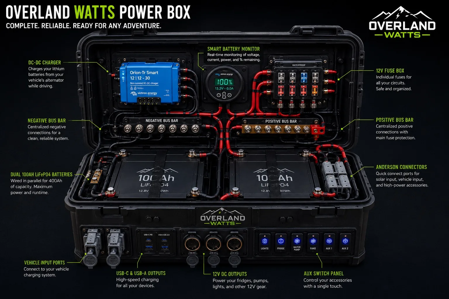
A clean build has a simple flow: vehicle input and/or solar charging feeds the DC-DC charger, the charger fills the LiFePO4 battery bank, the battery bank feeds a main fuse, the main fuse feeds the positive bus bar, the negative side returns through the shunt and negative bus bar, and the fuse block distributes protected power to each output or accessory circuit.
Step 1: Define the actual mission
Before buying parts, list what the box needs to run. A weekend fridge-and-lights box is very different from a Starlink, laptop, camera, fridge, water pump, heated blanket, and camp-lighting setup. Write down every load, its watts or amps, and how many hours per day it runs.
- Fridge or freezer
- USB-C laptop and phone charging
- 12V lights, fan, and water pump
- Air compressor or high-current tools
- Starlink or communications gear
- Heated blanket, diesel heater electronics, or winter accessories
Once you know the watt-hours per day, you can size the batteries, charging, fuse block, wire, and outputs instead of guessing.
Step 2: Choose the enclosure
Use a rugged enclosure with enough room for batteries, wiring bends, fuses, ventilation space, service loops, and future upgrades. A box that looks huge when empty gets crowded fast once you add two batteries, a DC-DC charger, bus bars, a shunt, fuse block, ports, heat shrink, cable glands, and mounting plates.
For a build this complex, the enclosure should have a strong lower tub, a removable internal mounting panel, gasketed lid, secure latches, and tie-down points. Do not mount heavy electrical components on a floppy lid. Put the real equipment in the lower box where it can be supported and protected.
Step 3: Build a removable mounting backer
Do not screw every component straight into thin plastic. Cut a backer plate from HDPE, aluminum composite panel, marine plywood sealed with paint, or another rigid material. The backer gives your charger, fuse block, shunt, and bus bars something solid to mount to.
Lay the parts on the backer before drilling. Leave finger space around fuses, room to remove covers, and enough wire bend radius that heavy cable is not fighting the terminals.
Step 4: Place the batteries low and secure
The two 100Ah LiFePO4 batteries should sit low in the lower half of the box. That keeps the center of gravity down and makes the box less likely to tip. Use straps, brackets, foam isolation, or a hold-down tray so the batteries cannot bounce around on rough roads.
If the batteries are wired in parallel, use equal-length positive and negative cables wherever practical. The cleaner the parallel wiring, the more evenly the batteries share load and charge current. Each battery should be protected according to the battery manufacturer’s manual.
Step 5: Install the main fuse close to the battery bank
The main fuse protects the cable leaving the battery bank. It should be as close to the battery positive connection as practical. If a downstream cable ever shorts to the case, frame, tool, or another conductor, the fuse is what prevents the wire from turning into a heating element.
Size the fuse for the cable and system design, not just the biggest number you can buy. The fuse must protect the wire. The wire must handle the expected current. The terminals must be rated for the same environment.
Step 6: Add positive and negative bus bars
Bus bars keep the system organized. Instead of stacking a pile of lugs on battery posts, route the main positive feed through the fuse to a positive bus bar, and route all returns to the negative bus bar through the shunt path.
Use covered bus bars with current ratings above your maximum expected current. Label the bus bars and leave room to tighten or inspect every connection later.
Step 7: Wire the smart shunt correctly
The shunt only works if every load and every charger returns through it. In a typical setup, the battery negative connects to the battery side of the shunt, and the system negative bus connects to the load side. If you accidentally connect some loads straight to battery negative, the monitor will not see that current and the state of charge will drift.
Mount the shunt where it is protected, dry, and serviceable. Keep the small sense wires tidy and protected from rubbing or accidental pulls.
Step 8: Install the DC-DC charger
The DC-DC charger is what makes alternator charging safe for LiFePO4 batteries. It limits current, regulates voltage, and prevents the house battery bank from abusing the starter battery or alternator wiring.
Mount the charger where it can shed heat. Follow the charger manual for wire size, fuse size, ignition trigger wiring, solar input rules, and charging profile. A 30A charger is common for builds like this, but the correct size depends on alternator capacity, cable length, battery bank size, and how fast you need to recharge while driving.
Step 9: Add vehicle input ports
Vehicle input ports let the box connect to the truck charging circuit. Anderson-style connectors are popular because they are rugged, keyed, and handle higher current than small barrel plugs.
Use weather-resistant panel mounts, strain relief, and a fuse or breaker at the vehicle battery side. The cable from the vehicle to the box should be protected wherever it passes through sheet metal, bed rails, drawers, or camper structure.
Step 10: Install the 12V fuse block
The fuse block powers the smaller branch circuits: lights, fridge outlet, water pump, fans, USB ports, aux switches, and other accessories. Each branch gets its own correctly sized fuse. That makes troubleshooting easier and prevents one fault from taking down the whole system.
Do not use the switch panel as a replacement for fuses. The fuse protects the wire. The switch controls the circuit. Both matter.
Step 11: Build the front output panel
The front panel should be useful at camp without opening the box. A strong layout includes USB-C, USB-A, 12V cigarette-style sockets, high-current Anderson connectors, and labeled aux switches.
Keep front-panel wiring short, protected, and strain relieved. Use rubber boots or covers for dusty and wet environments. If the box rides in a truck bed, assume vibration, dust, water spray, and accidental bumps will happen.
Step 12: Plan the wiring paths before cutting cable
Good wiring is mostly layout. Route red positive wires together, black negative wires together, and signal wires away from high-current cables when possible. Use grommets anywhere wire passes through a panel. Use clamps or tie mounts so cables cannot vibrate against sharp edges.
Leave service loops, but do not leave loose spaghetti. The best builds look calm when you open the box: every wire has a job, every fuse has a label, and every cable is supported.
Step 13: Crimp, heat-shrink, and torque correctly
High-current 12V systems depend on mechanical connection quality. Use the correct lug size for the wire and stud. Use a real crimper, not pliers. Seal lugs with adhesive-lined heat shrink where appropriate. Torque terminals to manufacturer specs, especially battery posts, bus bars, shunts, and fuse holders.
After the first few trips, inspect the box again. Vibration can reveal weak mounting, poor strain relief, or loose hardware.
Step 14: Test in stages
Do not connect everything at once and hope. Build and test in stages.
- Verify battery voltage and polarity.
- Connect the main fuse and bus bars.
- Confirm the shunt reads current in the correct direction.
- Power the fuse block with no loads installed.
- Add one output circuit at a time.
- Connect the DC-DC charger and verify charge current.
- Run a fridge or test load for several hours.
- Check cable heat, fuse holders, terminals, and charger temperature.
Step 15: Label everything
Label the fuse block, inputs, outputs, switch panel, and main disconnect points. A label that feels unnecessary in the garage becomes extremely useful when something stops working in the rain, at night, or halfway through a trip.
Suggested build order
| Phase | What to complete | Do not move on until |
|---|---|---|
| Layout | Mock up batteries, charger, bus bars, fuse block, shunt, and ports. | The lid closes and every terminal can be serviced. |
| Mounting | Install backer plates, battery hold-downs, port panels, and strain relief. | Nothing moves when the box is shaken. |
| Main power | Battery bank, main fuse, shunt, positive bus, negative bus. | Polarity and voltage are verified. |
| Distribution | Fuse block, output ports, aux switch panel, branch fuses. | Each circuit powers correctly by itself. |
| Charging | Vehicle input, DC-DC charger, optional solar input. | Charge profile and current are confirmed. |
| Trail testing | Run real loads, inspect heat, tighten hardware, label fuses. | The system survives a full test day. |
Final checklist
- Main fuse is close to the battery positive feed.
- Every positive branch circuit is fused.
- Battery bank is strapped down and isolated from rubbing.
- Shunt is wired so all current passes through it.
- DC-DC charger has correct input and output fuse protection.
- Front ports have weather covers and strain relief.
- Cables are supported, protected, labeled, and clear of sharp edges.
- No exposed positive terminals can contact tools, case hardware, or loose gear.
- The box has been tested under real load before a trip.